Buffer Operation
Computes a buffer area around the selected geometries.
The Buffer Operation takes the features from a source vector layer and creates a buffer area of a specified distance around, storing the result on a Result Layer.
If the source layer has features selected, the operation will be performed against them, otherwise, the features from the whole Layer will be used. The Source Layer is not modified by any means. A new Result Layer is created by default, or the user can specify an existing editable vector layer where to store the results.
Sample Usage
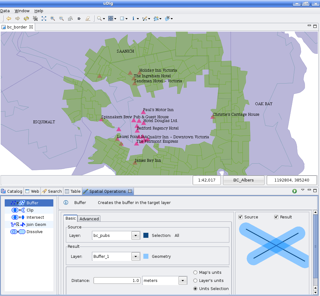
Go to the Spatial Operations View, and select Buffer from the Operation drop down.
The Buffer Operation’s specific input options will show up.
- Select the Source Layer: On the Source Layer drop down, select the Layer you want to create the buffered area from. By default, the currently selected Layer in the Layers View will be chosen for you.
- Select the Result Layer: The Result Layer drop down will contain a proposed Layer name for the Layer to be created to hold the operation’s results. You can leave it as is, type another Layer name, or select an existing Layer from the Result Layer drop down. In the later case, the operation’s result will be stored on the selected Layer.
- Set the Buffer Width and Units: At the Options section, specify the scalar value for the computation of the width of the buffer area around the source Features, and select which unit of measure the buffer width shall be considered in. You can choose between the current Map units, the Layer units or even to choose another unit of measure from the Units drop down.
Now you’re ready to go. Press the Perform button from the View’s tool bar and the operation will begin.
Once you press the Perform button, the operation progress will be shown up on a progress dialog.
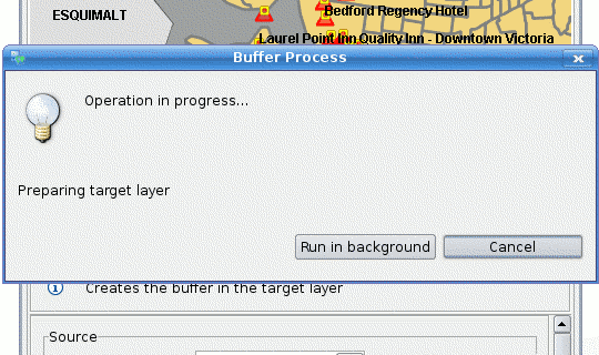
The operation may take a while to complete, depending on the amount and complexity of the input geometries.
Once the Operation finishes, if a new Layer were created to hold the result, it will be automatically added to the current Map.
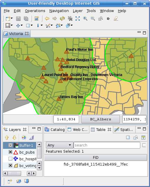
As shown above the newly created Layer (Buffer-1, in green) is added to the map, with one Feature whose Geometry is the aggregated result of applying the specified buffer to the default geometries in the source Features.
Advanced Options
The Buffer Operation contains a couple advanced options you can set to control certain aspects of the process.
The setting controls for the Merge Features and Segments per quadrant advanced options.
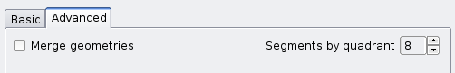
The Merge Features options controls whether to create a single aggregate geometry for the whole source Features set, or to create a new Feature in the Result Layer per source Feature. By default, this option is checked and a single aggregate Geometry is created. Shown below is the result (Buffer-2 Layer, in red) of applying the same buffer width than the example above, but with the Merge Features option unchecked.
The Segments per quadrant option allows a fine grained control over how many straight segments shall be used to approximate a quarter circle. This is parameter affects how the rounded areas over vertexes are built, as uDig uses linear approximations of curves.
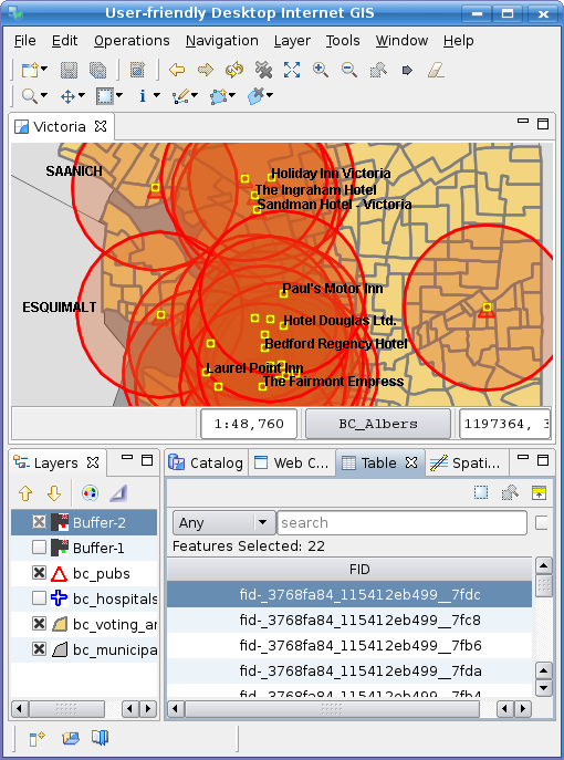
Shown above is the result of operation with * Merge Features unchecked.